29th January 2003
|
|
29th January 2003 |
|
|
La traduzione è ancora in corso
I assembled a standard 1.4 second pendulum Seismometer Kit supplied by Nuova Elettronica. The pendulum and the electronics work well, but I have not been able to get reliable near critical damping using the oil dash pot + paddle. In spite of what NE claim, the viscosity of motor oil varies quite dramatically over my ambient temperature range. Even heavy gear oil failed to produce adequate damping at the higher temperatures. After mopping up the second oil spillage, I decided to make an adjustable Electromagnetic Damping fixture, which is not temperature sensitive.
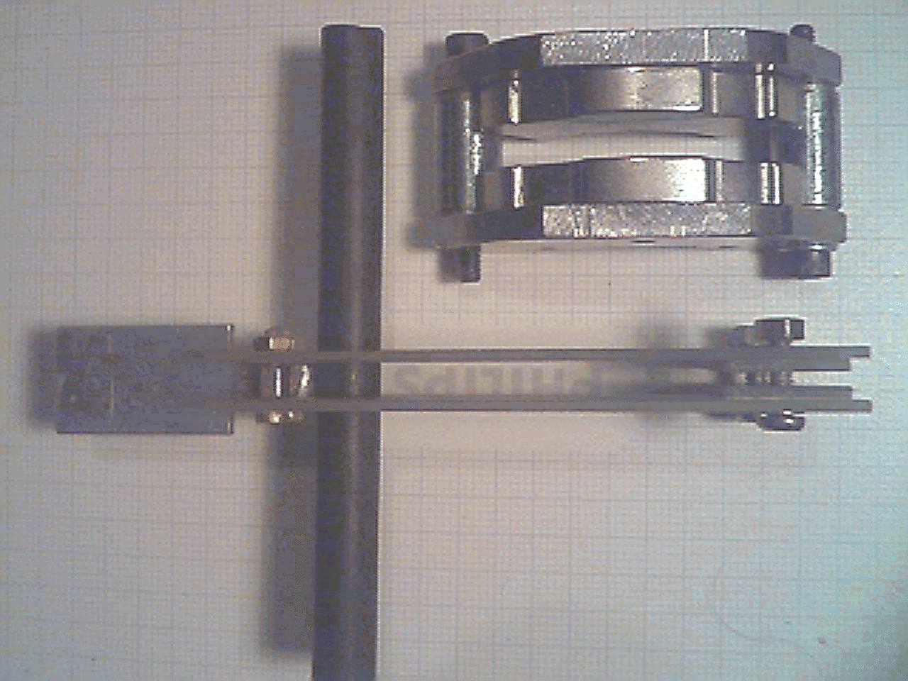
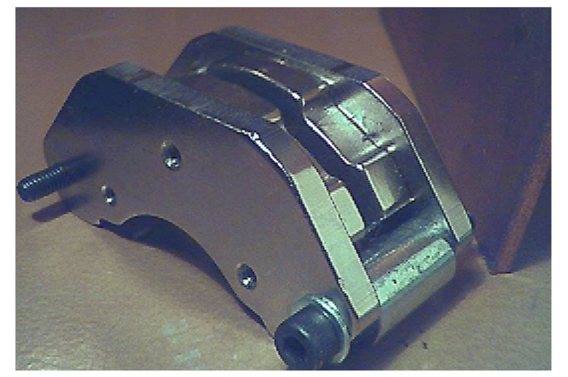
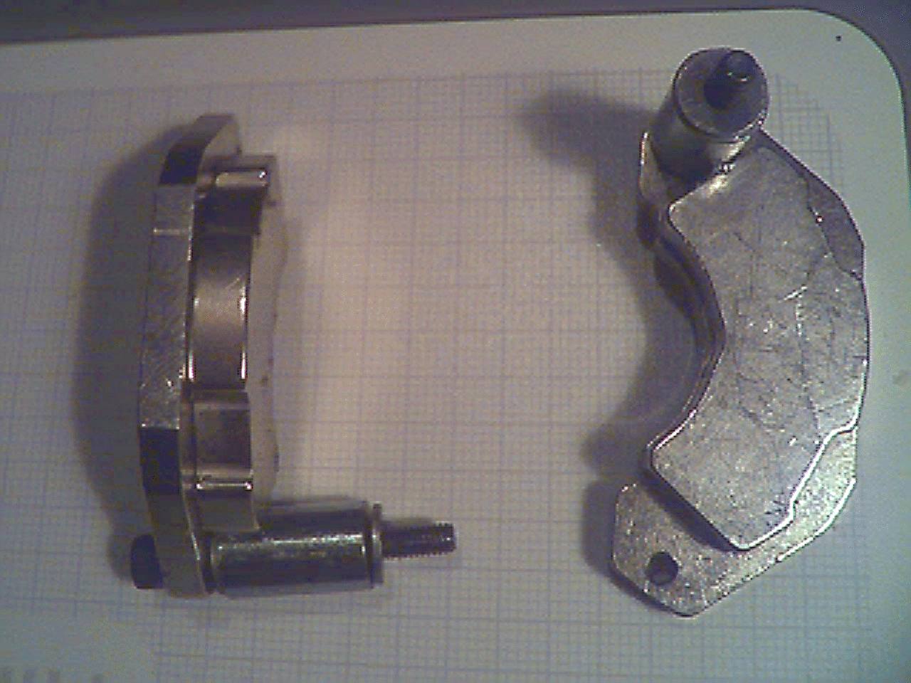
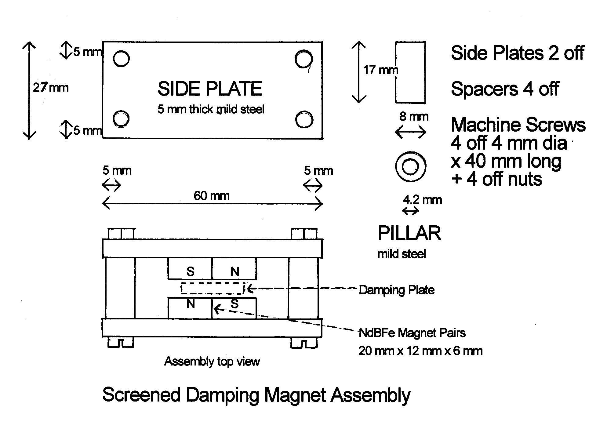
I removed the plastic oil dash pot and measured the space available above and below the printed circuit board. The pillar supports for the PCB are 30 mm high, so I designed the magnet housing to be 27 mm high. I obtained a pair of Type #31 NeBFe V shaped magnets on soft iron backing plates from www.wondermagnet.com They were used in computer hard drive mechanisms. The two arms of the magnet have adjoining N and S poles with a vertical join on the centre line of the V. I filed off a protrusion at the top of the soft iron backing plate so that it would fit under the circuit board. I bored and turned a pair of 10 mm dia soft iron pillars to act as magnet separators and clamped the magnets together with 4 mm dia bolts. A side view of the magnet assembly is shown in Fig 1 and a dismounted view is shown in Fig 2. Four of the Type #33 1" x 1/2" x 1/4" thick rectangular bars would probably have done equally well, but I would have had to make two 5 mm thick mild steel backing plates. The damping is concentrated around the central join in the magnets. A magnet thickness of 6 to 9 mm is desirable, to provide a strong enough field, although I have also used 20 mm x 10mm x 5 mm thick magnets.
The basic idea is to suspend a thick high conductivity Cu or Al plate in a region of intense magnetic field change. Any movement of the plate causes electrical currents to be induced which oppose the motion. The magnets are used in pairs in an enclosed a 'magnetic block' screen to give a low external field. This screening minimised any interaction with the ferrite rod movement sensor ~1.5 cm away. The two 5 mm thick soft iron backing plates are bolted together with 8 mm dia mild steel spacers at both ends to complete the 'magnetic block'. Provision was also made to add either flat or U shaped screening plates to the soft iron backing plates, but this proved not to be necessary.
I have also enclosed a drawing of an alternative magnet block 60 mm long by 27 mm high, which may be adapted to suit bar or cube NdBFe magnets that you may have available. The length of the spacers is chosen to give a gap of about 1 mm between the paddle and either polepiece. I initially tried using 1/2 mm gaps, but it proved quite difficult to observe the separation and to prevent the paddle from touching a polepiece during adjustment. This magnet arrangement gives a strong uniform field in the gap and the damping is nearly independant of the separation between the magnet faces and the damping plate. When in use, the bottom edges of the backing plates are in contact with the iron baseplate of the seismometer. There is a slight magnetic attraction to the baseplate and no additional fixing is required to keep the damping magnet block in position.
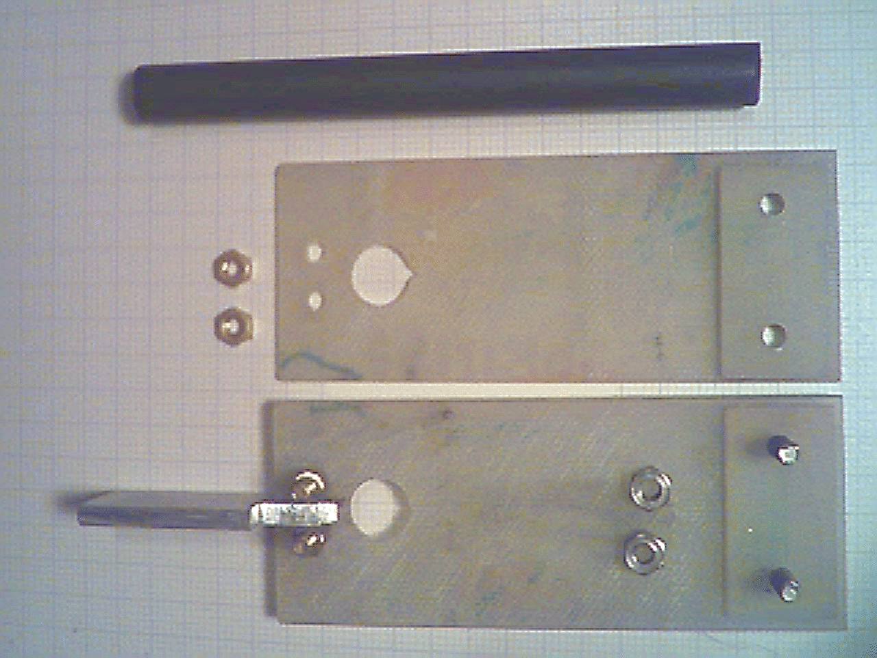
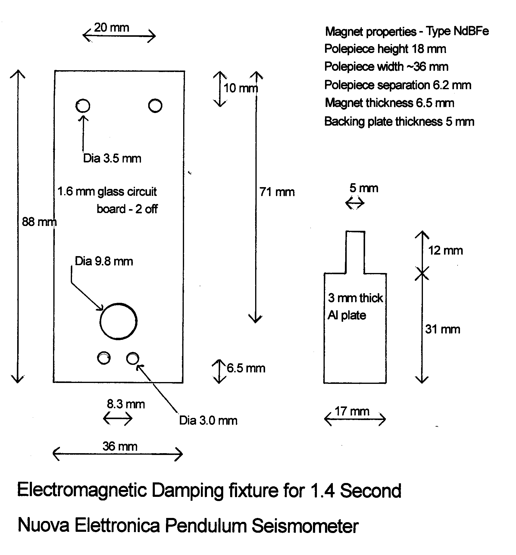
I made two shortened fibreglass plates from circuit board to suspend the ferrite rod from the pendulum bob and to fix the damping plate. The dimensions are given in Fig 4 and the complete damping assembly is shown in Fig 5. After cutting out and trimming the two new plates, I stuck them together with double sided tape and then stuck one of the original plates on top. I used the accurate holes in the original as a guide to drill the 3.5 mm and 9.8 mm holes in the new plates, using a press drill. I marked out, centre drilled and bored the two new 3 mm bottom holes for supporting the damping plate.
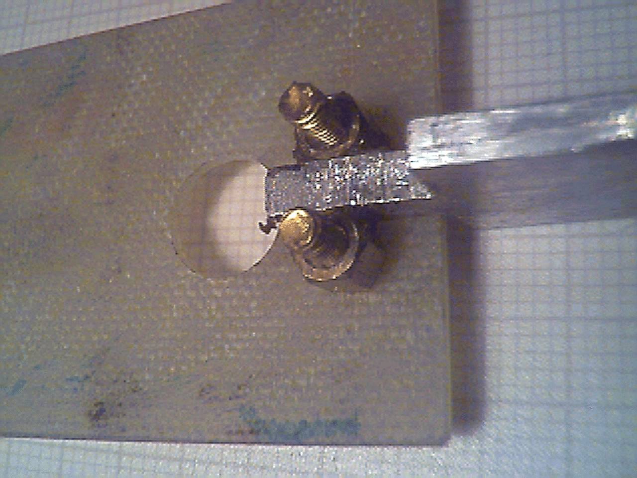
I cut out and hand finished the 3 mm thick soft Aluminum damping plate. Two 5 mm long hexagonal brass circuit board spacers are loosely secured to one plate with 12 mm long by 3 mm dia brass screws. The inner flat faces of the spacers and the matching faces of the tongue on the damping plate are coated with epoxy glue. The tongue is then slipped in between the spacers, aligned and the spacers are clamped to the tongue with a toolmaker's clamp. The brass screws are tightened and any excess epoxy is removed, see Fig 6.
To assemble, the magnet block is placed on the seismometer baseplate and the damping extension is held in position on the the pendulum. The magnet block is positioned so that the damping paddle is central and can swing freely. The extension is removed and the circuit board is fitted with the four securing nuts left loose. The damping extension is then fitted and secured. The ferrite rod is fitted and the circuit board is aligned so that the rod is centred in the coils. The four circuit board nuts are tightened. View the paddle with a small backlight through the removable side plate which carries the power line and output connectors. Check that it swings freely and evenly in the gap. Level the seismometer baseplate.
Switch
on the sensor and trim the position of the ferrite rod to give approximately
zero signal. Trim the levelling to give zero output. Deflect the pendulum
about 1 mm and release while watching the position meter, or record the
response. Slide the magnet block ~ 2mm parallel to the gap and repeat until
the indication shows a return to zero with a very small overshoot. Check
the paddle spacing after each movement. Then move the magnet block back
to give critical damping. Sliding the magnet block parallel to the gap
alters the position of the central field line and hence the area of field
coupled to the paddle. My pendulum can be adjusted from lightly damped
to very overdamped. Replace the side plate and the front cover.