LX922-LX1358
traduzione di Mauro Mariotti
27 Dicembre 2002
|
LX922-LX1358 traduzione di Mauro Mariotti |
27 Dicembre 2002 |
|
|
Parte 1 Considerazioni basilari
Ho avuto modo di costruire testare
ed usare il sensore LX1358 (LVDT) venduto in italia dalla rivista Nuova
Elettronica.
Il loro sito web è http://www.nuovaelettronica.it/
Il prezzo del kit è di E 51.65, in dollari circa $52 + spedizione,
il quale sembra un buon sensore. Il peso netto è di circa 12 once.
Il sensore è descritto nella rivista numero 195 Giungo-Luglio 1998.
Una figura del sensore da circa 1.4
secondi di periodo è disponibile a questo link
http://www.nuovaelettronica.it/it/pop/index.cfm?fb=scheda_kit&w.kit_id=1849
NE vende il kit completo di pendolo
che pesa circa 22 libbre. Vendono anche un sistema di monitoraggio a microprocessore
con un convertitore a 12 bit e una stampante termica, è disponibile
anche una interfaccia a 16 bit per collegamento al computer. (Nota
del webmaster: Questa interfaccia può essere pilotata anche tramite
SEISMOWIN e non solo tramite il programma che è fornito in dotazione
all'interfaccia)
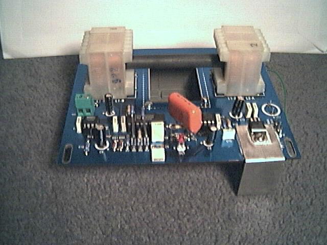
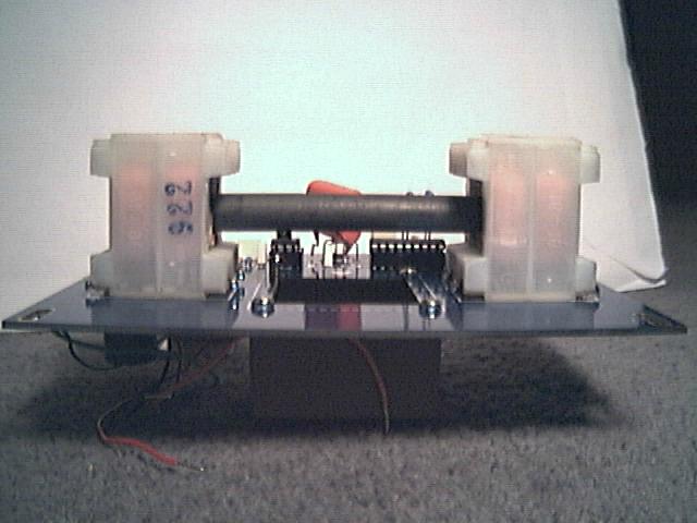
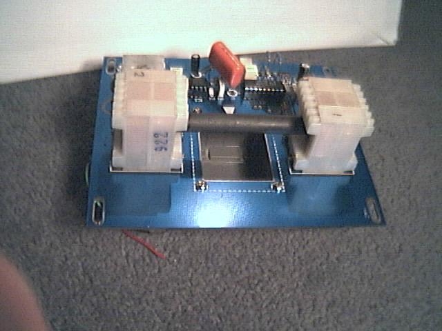
Il sensore LX1358 si può vedere
in fondo al contenitore in metallo con la barretta di ferrite posizionata
orizzontalmente tra le due bobine. La barra è tenuta sospesa dal
braccio del pendolo con due strisce di vetronite, le quali si immergono
anche nel contenitore di olio sottostante al circuito, olio che provvede
allo smorzamento.
Il kit include il circuito stampato,
quattro circuiti integrati, resistori e condensatori, diodi e uno strumentino
analogico, un contenitore in plastica per l'olio di smorzamento, due bobine
del sensore e la barretta di ferrite.
Il circuito può lavorare
con qualsiasi pendolo anche di tipo Lehman. Basilarmente il sensore fa
esattamente quello che ci si aspetta da esso.
Il principio di funzionamento è piuttosto semplice. La ferrite si muove all'interno due bobine identiche nelle quali le due estremità si introducono per circa metà della loro profondità. I rocchetti sono del tipo usato per i trasformatori a doppio isolamento con lo spazio per le due bobine di uguale dimensione. Gli avvolgimenti di magnetizzazione sono al lato interno della barra e le bobine di rilevazione si trovano al lato esterno. Un segnale sinosuidale preciso è applicato alle bobine primarie che sono conness in serie così che i campi magnetici si sommano nella barra di ferrite. Le bibine secondarie sono connesse in opposizione così il segnale si sottrae. Con la barra in posizione centrale non c'è uscita di segnale dalle bobine secondarie. Se la barra è mossa in modo assiale, la tensione idotta è ridotta da una delle bobine secondarie e aumentata dall'altra dando un segnale in uscita. Il segnale passa attraverso uno switch in fase con l'osscillatore il quale rettifica il segnale. Il segnale pulsante in uscita è introdotto in due filtri passa basso per livellarlo.
Questo segnale intermedio è un segnale in continua limitato in tensione equivalente a circa 0.3V per millimetro di movimento della barra. Per la regolazione della posizione della barra il segnale pilota uno microamperometro a zero centrale. La componente alternata passa attraverso un filtro passa alto ed è amplificata di circa 213 volte per avere il segnale finale in uscita. Questo permette di avere un rilevamento di posizione di circa +/-12mm, il che permette di avere una buona sensibilità anche su segnali sismici di elevara velocità.
Il circuito stampato a doppia faccta misura 14.5cm di lunghezze e 12.5 cm di larghezza e 1.8 mm di spessore e risulta di eccellente fattura. La posizione dei componenti e i numeri di riferimento sono stampati sul circuito. I sensori e l'elettronica formano una unica unità. Le bobine sono assemblate alle due estremità del circuito stampato dal lato posteriore. La barra in ferrite attraversa le due bobine e può essere facilmente usata per rilevare un movimento lungo l'asse delle due bobine. La vaschetta di plastica può essere fissata sotto al circuito stampato permettendo un 'oscillazione di circa +/-15mm.
Sulla scheda è predisposto
un regolatore di tensione di 12V che richiede un minimo di 14.5V d'ingresso
a circa 50mA (42.5mA misurati) di assorbimento. NE raccomanda un 24V dc
non regolato. Io ho usato un trasformatore miniatura da 15V 100mA a doppio
isolamento con due diodi e un condensatore da 1000 microFarad, che fornisce
circa 20V in continua non stabilizzati che consente di avere un certo margine
durante occasionali oscillazioni di tensione della tensione di rete.
Ho anche posizionato i componenti
in modo da proteggerli da scariche elettriche e transienti di rete. Questi
componenti e un fusibile, un LED e un interruttore sono stati montati separatamente
in una scatola schermata lontano dal sismometro. Si ha normalmente bisogno
di qualche protezione contro i transienti e una buona messa a terra per
eliminare i disturbi di rete presenti quali i disturbi provocati da elettrodomestici
come un banale frigorifero, eccetera.
Il circuito è progettato intorno al chip LVDT Philips NE5521. L'elettronica consiste di una sezione LVDT che produce una risposta lineare e continua calibrata a circa 300mV per mm di movimento. Questo è seguito da un filtro passa alto e da un amplificatore di circa 213x, dando una sensibilità finale di circa 65mV per micron. Il livello di rumore del circuito è inferiore a +/-0.5mV che corrisponde a circa +/-7 nanometri. Lo zero di riferimento è dato da circa la metà della tensione di alimentazione (6V). Per altre informazioni si consulti il circuito Philips presso il link http://www.semiconductors.philips.com/search/ cercando NE5521 nella casella di ricerca. Questo dovrebbe portare al data sheet e alla nota applicativa AN1182.
Per avere un range lineare superiore il sensore dovrebbe fisicamente essere più largo. Sono stati usati una barra di ferrite lunga 99mm e di 9.6mm di diametro e due trasformatori con luce interna di circa 3.5 centimetri cubi. Il peso della barra è di circa 35 grammi. Oggetti piuttosto robusti! Ma questo permette di avere un gap di circa +/- 3mm all'interno delle bobine il che è molto utile in fase di assemblaggio e allineamento e permette alla barra di oscillare liberamente.
L'uscita del sensore è lineare
rispetto al movimento fino a circa +/-6mm e l'uscita è inferiore
di un 10% fino a +/-12mm, è inutilizzabile oltre i +/-15mm. Questo
ampio range permette al sensore di essere usato anche come trasduttore
di un sismometro tipo Lehman, anche se, dato che questi sensori tipicamente
producono un segnale piuttosto ampio, il guadagno dell'amplificatore dovrebbe
essere ridotto.
In altre parole il braccio del sismometro
può oscillare di oltre un centimetro senza compromettere la rilevazione
del segnale.
Il filtro passa alto ha una costante di tempo di circa 1 secondo, che va bene per un sismometro a corto periodo ma è troppo bassa per in sismometro a "porta di giardino". Ho trovato che modificando il condensatore di disaccoppiamento e un resistore si può estendere la costante di tempo fino a 47 secondi senza problemi. Il circuito può anche essere modificato per differenziare la misura di spostamento in velocità. Questo può essere preferibile in sensori a lungo periodo di tipo Lehamn.
Per agevolare la regolazione del
bilanciamento e del punto zero e per controllare il drift, nel kit è
provveduto uno strumentino a lancetta. Questo è pilotato direttamente
dall'uscita dell'LVDT. Lo strumento è tarato sui +/-200microA a
740 ohm.
Come da progetto il senale di calibrazione
sullo strumento corrisponde a circa +/-0.2millimetri e +/- 1.2mm agli estremi.
Se pensate di usare questo sensore in una meccanica di tipo Lehman, potreste
trovare molto utile di incrementare il range massimo a +/-12mm o più.
Questo vi darà una maggiore estensione di lettura della posizione.
Inoltre è molto utile per controllare visivamente un eventuale modifica
del livellamento del sensore senza doverlo toccare.
Dato che io vivo in un'area dove
c'è un andamento intermittente di traffico e di disturbi ambientali
e che questi creano serie interferenze alle registrazioni sismiche, ho
deciso di investigare le caratteristiche del filtro LVDT. Il circuito usa
un filtro passa basso di tipo Sallen Key progettato per avere un certo
guadagno che da 3dB a 33Hz e 20dB a 250Hz. Il circuito sembra essere l'esatta
copia del circuito proposto dalla Philips nel datasheet del NE5521 per
applicazioni commerciali del suo LVDT. Ho cambiato tre resistori e un condensatore
per migliorare la reiezione al rumore oltre 10 Hz e date una risposta a
3 poli che crea un taglio di filtro molto più netto.
Ho misurato il nuovo punto a 3dB
a 10Hz e 20dB un poco sotto 20Hz, la frequenza di taglio può essere
abbassata come si desidera anche sotto 3Hz ma almeno due condensatori andrebbero
aggiunti a tale scopo. Ho usato condensatori poliestere di tipo miniatura
(bassa tensione n.d.r.).
Il mio sensore è alloggiato in un contenitore metallico ben schermato dai campi elettromagnetici esterni, comunque le barre di ferrite sono progettate per dare una efficace ricezione dei segnali radio e la frequenza di oscillazione dell'LVDT è di circa 15 kHz, questo rende possibili interazioni tra sensori non schermati e campi EMI a 15Khz prodotti da TV e monitor di computers nonchè da trasmettitori radio VLF. Ho controllato l'uscita del sensore per interferenze ai campi magnetici intorno ai 15 Khz e risulta piuttosto sensibile, ma la banda di ricezione è molto stretta. Se usate un sensore non schermato suggerisco che controlliate il segnale, potrebbe avere dei problemi di ricezione di segnali anomali. La frequenza dell'oscillatore è regolata da un resistore e un condensatore che possono essere facilmente modificati. La scelta della frequenza non è critica entro qualche kilohertz ma deve essere stabile. Il calcolo della frequenza è dato dal datasheet Philips. Il campo magnetico dalle bobine si estende di circa 7 centimetri oltre il bordo scheda.
Le bobine commerciali avvolte in aria per LVDT che ho usato hanno solo mezzo millimetro di differenza tra il diametro del rocchetto e il diametro interno della bobina. Questo rende abbastanza difficile regolare e mantenere l'allineamento, comunque Schaevitz produce degli LVDT con una distanza di un sedicesimo di pollice. Un articolo introduttivo si può trovare in: http://www.msiusa.com/schaevitz/pdf/lvdt/LVDT_Intro.pdf Il 050 HR è in aria libera con +/- 1.27 mm lo stroke è lungo 28.7 mm, e il 100 HR ha un rocchetto di +/-2.54 mm e uno stroke di 46 mm - vedi http://www.msiusa.com/schaevitz/pdf/lvdt/HR-Series.pdf
Schaevitz pubblica un articolo tecnico che dà alcuni dettagli incluse specifiche tecnhce per realizzare sensori LVDT sensors e sistemi a: http://www.msiusa.com/schaevitz/products/LVDT/signal.pdf
Potreste aver bisogno di registrarvi
per scaricare i documenti dal loro sito web.
Un altra descrizione sugli LVDT
con un Applet Java che mostra il funzionamento del trasformatore AC la
potete trovare presso: http://www.rdpe.com/displacement/lvdt/lvdt-principles.htm
Sarò felice di passare informazioni
ad altri sui filtri e su altre piccole modifiche che ho trovato in modo
sperimentale e che abbassano notevolmente il rumore e che possono aumentare
la banda passante del sensore fino ad un periodo di 47 secondi.
Queste informazioni sono frutto
delle mie personali sperimentazioni e non sono state discusse con Nuova
Elettronica, non ho collegamenti con questa rivista se non quello di essere
un utente soddisfatto. I suggerimenti non devono essere interpretati come
critiche ai dispositivi di Nuova Elettronica o ai loro progettisti, il
kit originale che ho acquistato funzionava perfettamente ma funziona molto
meglio ore dopo la modifica di qualche componente.
This account gives details of some of the modifications which I have tried on my Type LX1358 LVDT sensor, marketed as a Kit by Nuova Elettronica. By experiment, I have found it possible to significantly lower the circuit noise and I have also been able to increase the time constant of the output from 1 second up to 47 seconds. This information, which I believe to be correct, is supplied as experimental notes in good faith but without any warranty or liability, either direct or implied. The suggestions are the result of my personal experiments and I have not discussed the circuit changes with Nuova Elettronica. I have no connection with Nuova Elettronica other than as a customer. The suggestions should not in any way be interpreted as a criticism of Nuova Elettronica equipment or designers.
Nuova Elettronica is an Italian Company which produce a wide range of Electronic Kits. Details of the Kits are published in their monthly Magazine. They marketed a 'garden gate' seismometer Kit which appeared in Issues 130-131 in May-June 1989. This featured the LVDT sensor Type LX922 and a microprocessor monitoring system with a thermal printer. A 1.4 second vertical pendulum seismometer Kit was described in Issue 195 of June-July 1998 and is still available. This featured the replacement LVDT Type LX1358 sensor, with an upgraded computer and printer system.
A Linear Variable Differential Transformer sensor is an excellent technical choice since it guarantees the linearity of response and also a very high sensitivity for a wide range of displacements between the seismic mass and the ground. The LX1358 sensor was originally designed to interface to a 12 bit A/D converter and some modifications are required to get optimum performance when it is used with a 16 bit A/D converter. The changes described relate to improvements in the stability, a reduction in the circuit noise, narrower band filters to exclude environmental noise and the use of integrated circuits with improved specifications.
I built the LX1358 and then used it unmodified on an NE 1.4 sec damped
pendulum.
The circuit is designed to drive a 0 to +10 V 12 bit A/D converter, with appropriate noise levels. Most current computer logging systems, like mine, use +/-10 V input 16 bit A/D Converters. The x8 increased resolution showed up significant circuit noise. The on board regulated power line is ~12 V DC and the signal zero reference line is approximately half this. This signal reference is set by two resistors in the NE5521 chip and the line is buffered by a TL081 opamp. The output opamp is a CA3130.
Modification 1
The
final CA3130 opamp will drive the output from line to line, but it is an
excessively noisy device. If you do need the line to line output drive
capability, a TLC2201, while a bit more expensive, is vastly preferable.
If you are re-referencing the output to 0 V and maybe adding additional
gain and filtering, an OP07 works well. A TL071 or a LF411 will also work
here, but their drift and noise are inferior to an OP07.
Modification 2
A
more thorough study of the output noise revealed that the TL081 reference
line buffer amplifier contained measurable amounts of 100 Hz hum as well
as quite a lot of hash noise. This was feeding through the output opamp
with the signal, since the +ve input line of the CA3130 was filtered by
4.7 K resistor and a 10 mu F capacitor. This opamp was changed to an OP07.
The capacitor from earth to the centre of the resistor chain was changed
from a 4.7 mu F electrolytic to a 47 mu F low leakage electrolytic and
a 47 mu F Tantalum was connected from the opamp output to earth.
Modification 3
I
have a site with a lot of environmental noise and passing trucks showed
up vibrantly on the recordings! Since I had no wish to monitor road traffic,
I decided to investigate the built in filter characteristics of the Sensor.
I had some difficulty in understanding the frequency design of the phase
detector circuit, so I measured the response. The readings were 3 dB down
at 33 Hz, 6 dB down at 49 Hz and 20 dB down at 254 Hz. This is not too
good for seismic use and will allow environmental noise (including cars
and lorries) to be detected with ease. Environmental noise may be serious
at frequencies above about 20 Hz. NE seem to have copied the Phillips data
sheet circuit which was designed for commercial LVDT applications, but
have not altered the filter. I changed three resistors and a capacitor
to improve the noise rejection above 10 Hz and to give a three pole response
with a much sharper cut-off. I measured the new 3 dB point at 10 Hz and
the 20 dB point at a bit under 20 Hz. The cut-off frequency may be lowered
still further if desired, to below 3 Hz, but two additional capacitor changes
are needed. Miniature polyester capacitors with a 5 mm pin spacing are
used. I measured the output impedance of the phase sensitive detector,
pin 5, at 1.8 Ohm, so it does not effect the value of the input filter
resistor R3. It is a voltage in / voltage out, direct / inverted, switched
unity gain circuit.
There are three high frequency limiting circuits. The two pole active filter with C5 and C6 is the first, the capacitor C12 is connected in parallel with the feedback resistor R11 on the output amplifier and there is the R12 / C15 filter on the final output. R11 / C12 has a design rolloff frequency at 3.4 Hz. The final filter R12 / C15 has a rolloff of about 1,600 Hz. I am puzzled by this high value. It may have originally been provided to ensure the stability of the CA3130 from the effect of output cable capacity, but it did not prevent some noise aliasing from effecting my 16 bit A/D converter. I decided to re-calculate the overall response as a 3 pole filter and to use R11 / C12 as necessary to balance the rolloff of the high pass filter / differentiator circuit. The third low pass pole, R12 / C15, ia applied across the output where wide band + 100 Hz noise on the reference line is more serious.
Considering
the three pole active filter, you have the choice of:-
a)
keeping the same two pole filter capacitors C5 and C6 or
b)
using increased capacities to lower the noise and / or the frequency rolloff.
It is desirable to limit the resistor values used in the filter circuit since the auxiliary opamp has a nominal input bias current of 0.21 micro Amp, max 0.6 micro A and a max. offset current of 50 nA. eg A 44 K Ohm input gives a typical offset of 9.24 mV, which appears on the output as a 32.8 mV error.
I calculated the following 10 Hz cut-off filters.
a) R3=24K, R6=20K, C5=470 nF polyester (supplied), C6=1 muF polyester (supplied), R12=1.5K, C15=10 muF solid Al electrolytic, C12=1.5 nF polyester
Rather surprisingly, I did not see an internal noise increase over the standard design with these larger value input resistors. The decrease in bandwidth seems to compensate for any increase in resistor or input current noise. No figures are available for the noise level of the auxiliary amplifier in the NE5521N chip. The electrolytic capacitor C15 should be measured / selected. Solid Al capacitors are preferable to a wet Al electrolytic. It may be necessary to trim the value of R12 to provide the 0.015 sec time constant, since the capacitor has a 20% tolerance. You will also need to recalculate R12 if a resistive output attenuator is used.
b) R3=4.4K, R4=22 K, R5=56K, R6=7.9K,
C5=2.2 muF polyester, C6=3.3 muF polyester, R12=1.6K, C15=10 muF solid
Al electrolytic, C1=1.5 nF polyester
This may
be a better design. 3.3 mu F is the largest capacity that you can buy in
miniature polyester capacitors with 5 mm pin spacing. (The components should
be of appropriate size for the board, if at all possible.)
The
resistor values may also be increased to give a cut-off frequency just
below 3 Hz without running into noise / drift problems.
c) R3=15K, R4=55 K (=33 K + 22 K),
R5=140 K (=130 K + 10 K), R6=27K, C5=2.2 muF polyester, C6=3.3 muF polyester,
R12=5.4K, C15=10 muF solid Al electrolytic, C1=4.7 nF polyester. The increased
values of the gain resistors R4, R5 are to match the input impedances to
both filter amplifier inputs. This reduces the offset voltage caused by
the rather high input currents.
Modification 4
The
output of the two pole filter, pin 1 on IC1, is shown connected to the
22 mu F electrolytic condenser C7 and a 47 K Ohm resistor R9 into the inverting
input of the output amplifier IC3. This choice seems to have been made
for the original LX922 sensor when a 0 to +5V 8 bit A/D converter was used.
The zero reference level used was then +2.5 V, so the electrolytic capacitor
was correctly biassed. With the change in reference level to +6V for the
LX1358, this capacitor may be reverse biassed by up to 5V.
The feedback resistor on IC3 is 10 Meg Ohm. An electrolytic capacitor has a typical leakage current of 0.01xCxV. For 5V and 22 mu F, this is ~1.1 micro A, which would give an 11 V leakage error on the output! I noted a very considerable offset and increased noise. I did not consider this to be satisfactory and I replaced C7 with a polyester capacitor.
You can buy 10 mu F 63 V rectangular polyester capacitors, but they are large and not exactly cheap. I considered three possible 'fixes' for the capacitor problem. Realising that I might wish to make circuit changes, I soldered terminal pins into the board at the positions marked R3, R4, R5, R6, R10, C7, C8 and C15 and then soldered the components to the pins. This avoided possible damage to the board when replacing components.
If you are using a short period vertical pendulum of ~1.4 sec period or less, substituting a 4.7 mu F polyester capacitor for C7 should be quite satisfactory.
If you are using a Lehman, you may choose a much smaller polyester capacitor, down to about 0.33 mu F minimum. This acts to differentiate the displacement signal to give a velocity output. This works OK because the horizontal displacement is generally greater at low frequencies. Some additional gain may be required. A 'compromise' value up to ~2 mu F may also be tried.
However, with the terminal pins inserted as described, it is possible to rewire the board to give a long period output of up to 47 sec.
The input is transferred from the -ve input of IC3 to the +ve input. C7 and C8 are removed / not wired in. A 4.7 mu F polyester capacitor is soldered between the +ve terminal pin of C7 and the +ve terminal pin of C8. R10 is replaced with a resistor of 100 K Ohm to 10 Meg Ohm to give the time constant required. The -ve terminal pin of C7 which is connected to R9, is wired to the +6 V reference line. I also soldered a reversed polarity diode across the input pins of IC3 to give 'back to back' signal input protection.
Modification 5
The measured
oscillator frequency was 15,030 Hz with a 12.13 V supply. A 4.7 nF polyester
capacitor and a 10 K Ohm resistor were supplied. Philips emphasise that
the oscillator components need to have a high stability. A simple test
with hot air from a hair drier showed more drift with temperature than
I liked, so I changed the resistor to 20 K Ohm 1% metal film and the capacitor
to 2.2 nF + 150 pF 1% polystyrene foil. Philips recommend a resistor of
18 K Ohm, but without saying why. This resistor sets the current through
the oscillator switched current sources and I assume that ~this value gives
the best linearity / lowest harmonic content.
Modification 6.
With
a power supply of 24 V, the on board voltage regulator will dissipate 0.4
Watt and feels warm to the touch. One of the major problems with highly
sensitive seismometers is that they can be disturbed by very small air
motions within their thermally insulated enclosure and 'hot spots' need
to be avoided. I fitted a U shaped Al strap between the PCB and the regulator
and bent it so that the other end was in good thermal contact with the
steel baseplate. This seems to have greatly reduced the temperature increase
of the voltage regulator.
I have a distance calibrator which gives an accurate measurement of movement over a range of 25 mm. I used a digital voltmeter to measure the voltage between the output of the NE5521 on pin 1 and the 6 V line and moved the ferrite rod 1 mm in between each measurement. This gave me an accurate linear calibration for the output of my sensor of 307 mV / mm over a range of +/- 6 mm. The output sensitivity decreased by 10% at +/- 12 mm and it was 20% down at +/- 15 mm. Any changes / noise in these voltage levels are amplified by x213 and output. The oscilloscope trace showed a peak to peak noise output signal over 10 seconds of approximately +/-0.5 mV, which corresponds to about +/-7 nanometres. This was of the same order as the 0.305 mV per digit of my 16 bit A/D converter. Overall, I am very pleased indeed with the results.
I
just wish that the environmental noise that I experience allowed these
excellent detection levels to be meaningful, but I am sure that others
will be more fortunate!